Difference between revisions of "Battery Power"
Alexalspach (Talk | contribs) |
Alexalspach (Talk | contribs) |
||
| Line 1: | Line 1: | ||
| − | {{TODO}} | + | As shown below, the [[power management system]] can be powered separately from the [[motor controllers]] and [[motors]]. While both require 24VDC, this isolation and use of separate power supplies allows the motor power to be disabled while leaving the [[internal computer]] and every other component running unaffected. |
| + | |||
| + | # The 24VDC line for the '''motor controllers and motors''' requires the use of eight (8) connector pins (4 positive, 4 negative). Multiple pins are used for each pole to handle the current necessary to run the dog under extreme conditions. | ||
| + | # The other 24VDC line powers the '''power management system, computer, and other accessories including sensors'''. This line requires only two (2) pins within the connector (1 positive, 1 negative). | ||
| + | |||
| + | |||
| + | {{pms power note}} | ||
| + | |||
| + | |||
| + | See below the Allegro Dog's power connector pin map and wiring diagram for using a tethered power supply. | ||
| + | |||
| + | {{TODO|Change text to reflect battery info, not external. just a placeholder.}} | ||
| + | |||
| + | |||
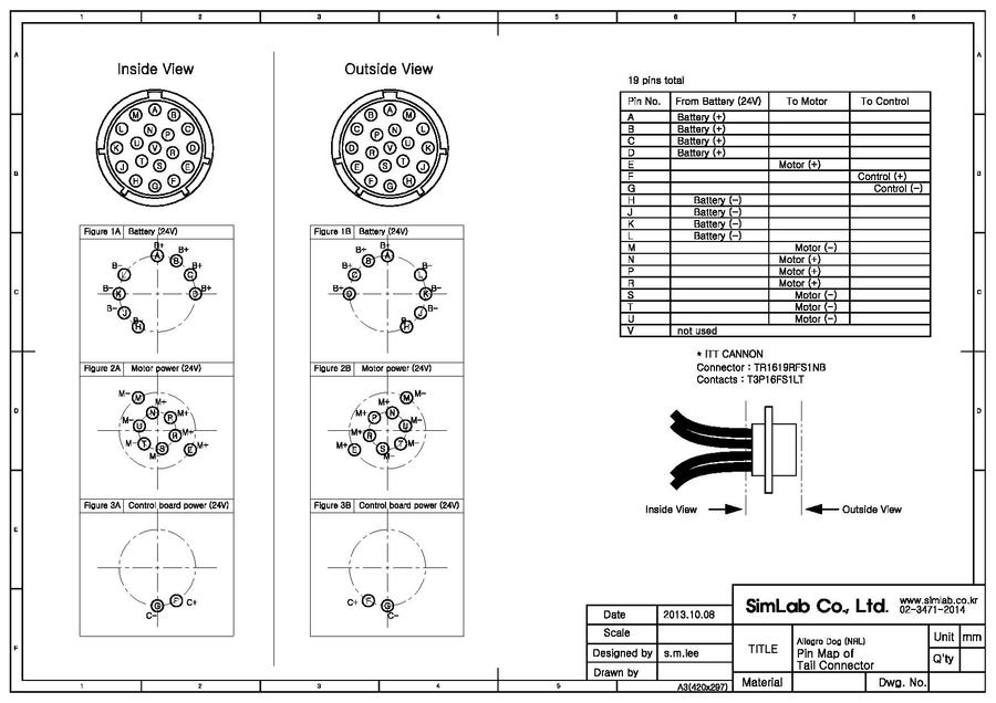
| + | ==Power Connector Pin Map== | ||
| + | {{pdf|Power_Connector_Pin_Map}} | ||
| + | |||
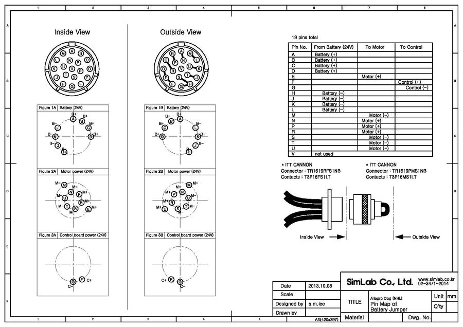
| + | ==Battery Jumper Plug== | ||
| + | {{pdf|Battery_Jumper_Plug_Pin_Map}} | ||
| + | |||
[[Category:Hardware|B]] | [[Category:Hardware|B]] | ||
[[Category:Electronics|B]] | [[Category:Electronics|B]] | ||
[[Category:Power|B]] | [[Category:Power|B]] | ||
Revision as of 17:37, 13 November 2013
As shown below, the power management system can be powered separately from the motor controllers and motors. While both require 24VDC, this isolation and use of separate power supplies allows the motor power to be disabled while leaving the internal computer and every other component running unaffected.
- The 24VDC line for the motor controllers and motors requires the use of eight (8) connector pins (4 positive, 4 negative). Multiple pins are used for each pole to handle the current necessary to run the dog under extreme conditions.
- The other 24VDC line powers the power management system, computer, and other accessories including sensors. This line requires only two (2) pins within the connector (1 positive, 1 negative).
Note When power is supplied to the power management system it will automatically turn on without any further action from the user. It is only powered off when the power supply is removed. Powering the internal computer and motor controllers requires further action.
See below the Allegro Dog's power connector pin map and wiring diagram for using a tethered power supply.
TODO: Change text to reflect battery info, not external. just a placeholder.
Power Connector Pin Map
Battery Jumper Plug