
Difference between revisions of "Motor Controllers"
Alexalspach (Talk | contribs) |
Alexalspach (Talk | contribs) |
||
| Line 9: | Line 9: | ||
{{pdf|CAN Protocol|400px}} | {{pdf|CAN Protocol|400px}} | ||
| − | ==Wire Routing== | + | ==CAN Wire Routing== |
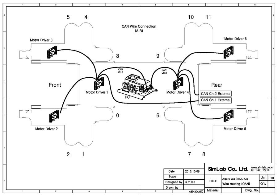
{{pdf|CAN_Routing_A_B}} | {{pdf|CAN_Routing_A_B}} | ||
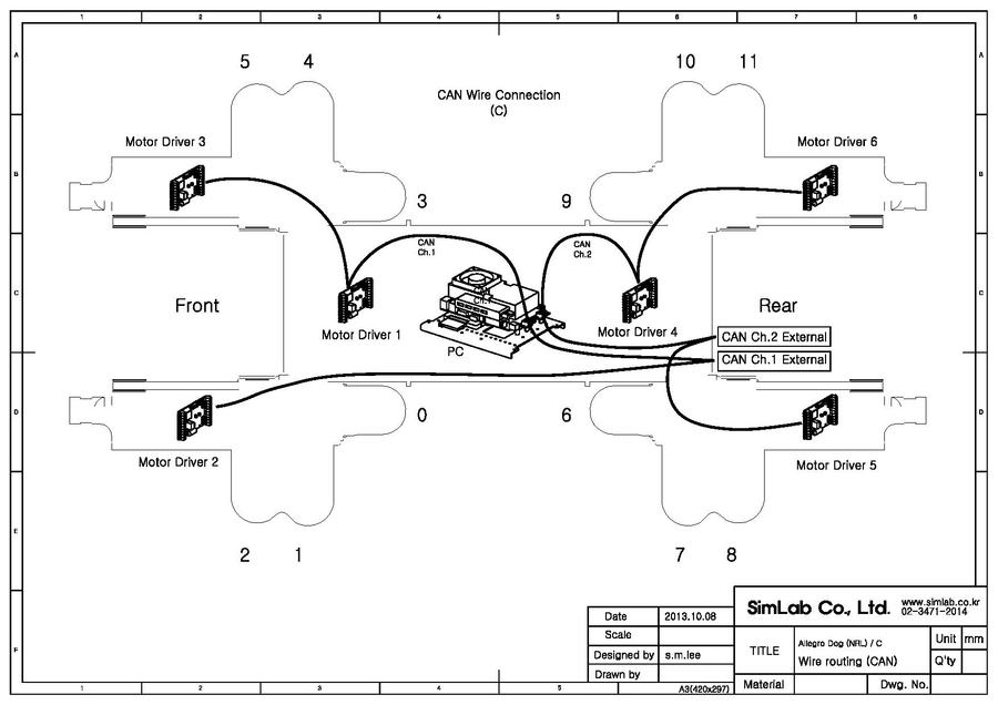
{{pdf|CAN_Routing_C}} | {{pdf|CAN_Routing_C}} | ||
| + | |||
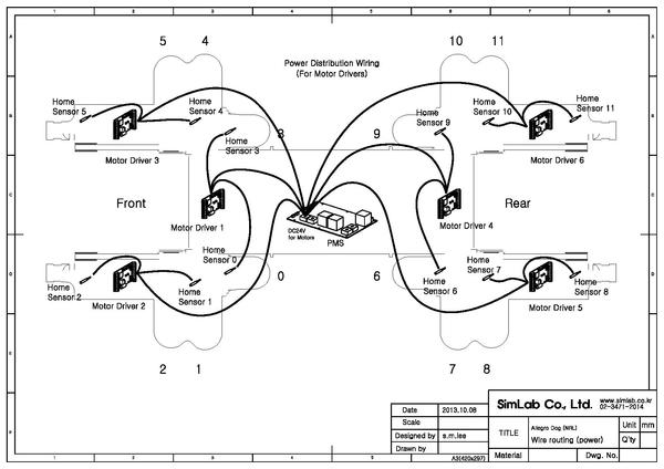
| + | ==Power Wire Routing== | ||
| + | {{pdf|Motor Controller Power Routing|600px}} | ||
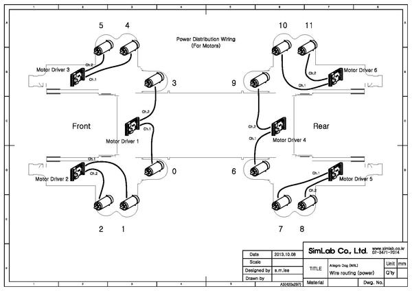
| + | {{pdf|Motor Power Routing|600px}} | ||
| + | |||
{{More Info}} [[Motor Controller Power]], [[CAN]], [[Wiring]] | {{More Info}} [[Motor Controller Power]], [[CAN]], [[Wiring]] | ||
Latest revision as of 14:05, 9 December 2013
Contents |
Pin Out

| No. | Name | Function |
| 1 | CANH / SCI+ | RS485 / CAN Communication Positive Signal |
| 2 | CANL / SCI- | RS485 / CAN Communication Negative Signal |
| 3 | AGND | |
| 4 | LS1C / VELO1 | |
| 5 | LS2C / VELO2 | |
| 6 | LS1D / FAULT1 | |
| 7 | LS2D / FAULT2 | |
| 8 | +24V / +36V / +48V | DC Power Positive (Controller and Home Sensors) |
| 9 | PGND | DC Power Ground (Controller and Home Sensors) |
| 10 | N.C / Vcon | |
| 11 | LS1A | |
| 12 | LS1B | Home Sensor Signal (Ch. 1) |
| 13 | DGND | |
| 14 | MOT1+ | Motor Power Positive (Ch. 1) |
| 15 | MOT1- | Motor Power Negative (Ch. 1) |
| 16 | MOT2+ | Motor Power Positive (Ch. 2) |
| 17 | MOT2- | Motor Power Negative (Ch. 2) |
| 18 | DGND | |
| 19 | LS2A | |
| 20 | LS2B | Home Sensor Signal (Ch. 2) |
| ENC1 | Encoder (Ch. 1) | |
| ENC2 | Encoder (Ch. 2) |
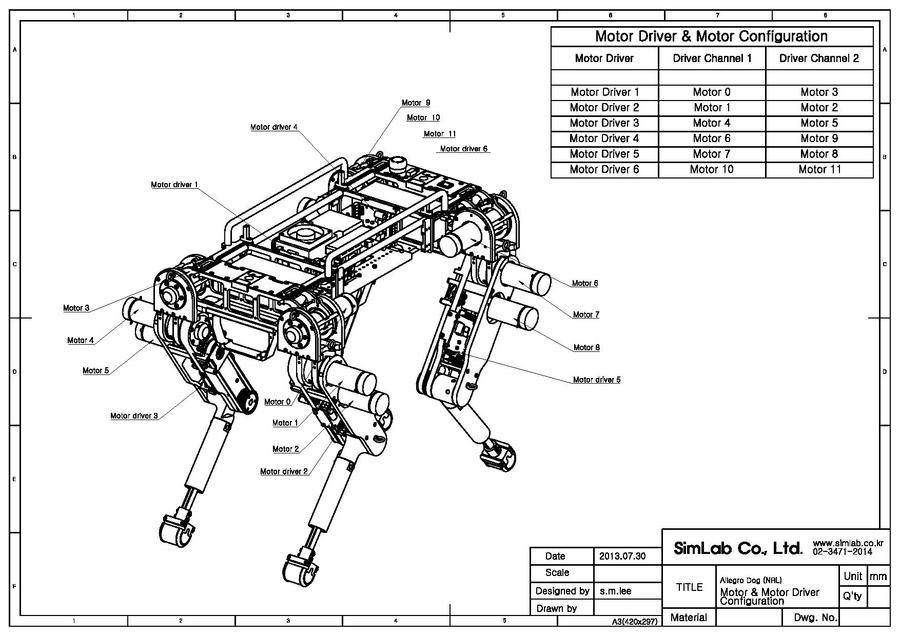
Motor Controller and Motor Numbers
Communication Protocol
CAN Wire Routing
Power Wire Routing
More Information: Motor Controller Power, CAN, Wiring