
Difference between revisions of "Overview"
Alexalspach (Talk | contribs) (→Internal Computer) |
Alexalspach (Talk | contribs) (→Power Management System) |
||
| Line 79: | Line 79: | ||
===Power Management System=== | ===Power Management System=== | ||
| + | |||
| + | {{Power Management System Intro}} | ||
| + | |||
| + | {{pms power note}} | ||
===External Power Requirements=== | ===External Power Requirements=== | ||
Revision as of 21:47, 21 November 2013
Contents |
Wiki Structure
The Allegro Dog Wiki is broken up into separate sections, or categories, to help in locating necessary information quickly and easily. Below you can see the top-level parent categories, the hierarchical structure and articles each category contains.
More Information: About this Wiki
Booting the Allegro Dog
Multiple steps must be taken to properly and safely boot up and run the Allegro Dog internal computer and hardware. The following instructions should be followed closely. If you need any help, please contact us.
Note Refer to the Control-I/O Panel diagram for switch, button and indicator locations.
- Elevate the Allegro Dog
- Supply Required Power (24VDC)
- Flip On Main Power Switch
- Turn Computer On
- Release Emergency Stop
- Turn Motor Controller Power On
- Establish Remote Connection
- Run the Included Software
- Find Encoder Offsets (Homing)
- Enable Motor Control
- Assume Ready Position
- Walk Around
Full Booting Instructions Control-I/O Panels
More Information: Full Booting Instructions, Control-I/O Panels
Software
The Allegro Dog comes pre-installed with SimLab's RoboticsLab™ and the RealtimeRobotics™ realtime add-on. This allows you develop Allegro Dog controllers and test them on the system in hard real time.
To facilitate the productivity of robotics researchers and engineers, RoboticsLab™ aims at providing systematic support for the whole spectrum of development from prototyping to the robust control of hardware systems. Every aspect of our software and its use has been examined from the viewpoint of the robotics engineer, greatly reducing the need for specialized knowledge in the low-level details.
RealtimeRobotics™ is a RoboticsLab™ Premium Add-on which implements a commercial RTOS-based real-time control framework for RoboticsLab™.
More Information: Software, RoboticsLab, RealtimeRobotics, Allegro Dog VS Project
Hardware
The hardware section of the Allegro Dog wiki includes mechanical and electrical system information as well as assembly and maintenance information.
More Information: Hardware
Component Overview
The drawings contained in this section point out the high-level components of the Allegro Dog.
More Information: Component Overview
Kinematic Information
Joint Limits
Link and Joint Dimensions
Dynamic Information
Link Masses
Link COMs
Link Inertia
Joint Locking
Joints can be locked into a stable "kneeling" position for storage or shipping.
More Information: Joint Locking
Mechanical Drawings
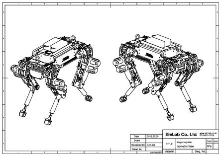
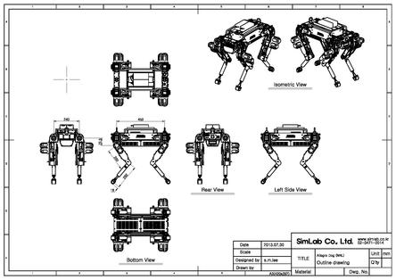
Click here to see all Orthographic Drawings.
Computer
The Allegro Dog's internal computer is an Advantech MIO-5290 single board computer (SBC).
The Allegro Dog can be controlled in realtime using an external computer with RoboticsLab™ and RealtimeRobotics™ installed via CAN interface.
More Information: Internal Computer, External Computer
Power
The external power port is used to supply external power or redirect battery power to the Allegro Dog. It accepts two separate 24V inputs: One input powers the power management system and the second powers the motor controllers and motors.
More Information: Power, Power Management System,
Power Management System
The Allegro Dog's power management system provides power to every Allegro Dog component. A 24V/A output powers the motor controllers and motors while a separate 24V/B line and 12 and 5V lines power the internal computer, IMU and any other devices added to the system. The power management system also limits the current supplied to the various devices and helps keep batteries healthy by limiting their drain.
Note When power is supplied to the power management system it will automatically turn on without any further action from the user. It is only powered off when the power supply is removed. Powering the internal computer and motor controllers requires further action.