
Overview
Contents |
Wiki Structure
The Allegro Dog Wiki is broken up into separate sections, or categories, to help in locating necessary information quickly and easily. Below you can see the top-level parent categories, the hierarchical structure and articles each category contains.
More Information: About this Wiki
Booting the Allegro Dog
Multiple steps must be taken to properly and safely boot up and run the Allegro Dog internal computer and hardware. The following instructions should be followed closely. If you need any help, please contact us.
Power Sources
The Allegro Dog runs on 24VDC, and under normal conditions draws no more than 20 amps. The current required varies greatly with the algorithm and application. The dog can be powered via external power supplies or by multiple internal and external batteries.
Note When power is supplied to the power management system it will automatically turn on without any further action from the user. It is only powered off when the power supply is removed. Powering the internal computer and motor controllers requires further action.
More Information: Power Sources
Main Power Switch
Available directly off of the Allegro Dog's internal power management system are 24V/B, 12V and 5V internal power sources.
More Information: Internal Power Sources
Computer
- Internal Computer
- The Allegro Dog's internal computer is an Advantech MIO-5290 single board computer (SBC).
- External Computer
- The Allegro Dog can be controlled in realtime using an external computer with RoboticsLab™ and RealtimeRobotics™ installed via CAN interface.
More Information: Computer
Emergency Stop
The emergency stop switch kills the 24V/A supply of power to the motor controllers and motors. The switch affects nothing else in the system. When triggered, the computer and any other devices supplied by the 24V/B, 12V or 5V internal power sources will remain active.
More Information: Emergency Stop
Motor Controller Power
The motor controllers and motors are powered via the power management system's 24V/A output. Power to the motor controllers can be turned on using the Motor Controller/Motor Power Switch (No. 8 on the Control-I/O Panels) or the wireless remote.
More Information: Motor Controller Power
Remote Connection
Remote Connection
Homing
When the Allegro Dog is first powered on a simple homing procedure must be executed to find the offsets necessary for the incremental (relative) encoders at each joint. This procedure must be followed before the joints can be properly and safely controlled.
The homing procedure slowly jogs each of the 12 joints until a homing sensor is activated and deactivated. The angular displacement between the start of this procedure and the sensor activation is used to determine the offset necessary to properly locate each joint's zero position.
Note Every time the Allegro Dog is powered on (every time the motor controllers lose and regain power), the joint offsets must be found again using the homing procedure.
More Information: Homing
Software
The Allegro Dog comes pre-installed with SimLab's RoboticsLab™ and the RealtimeRobotics™ realtime add-on. This allows you develop Allegro Dog controllers and test them on the system in hard real time.
To facilitate the productivity of robotics researchers and engineers, RoboticsLab™ aims at providing systematic support for the whole spectrum of development from prototyping to the robust control of hardware systems. Every aspect of our software and its use has been examined from the viewpoint of the robotics engineer, greatly reducing the need for specialized knowledge in the low-level details.
RealtimeRobotics™ is a RoboticsLab™ Premium Add-on which implements a commercial RTOS-based real-time control framework for RoboticsLab™.
More Information: Software, RoboticsLab, RealtimeRobotics, Allegro Dog VS Project
Hardware
The hardware section of the Allegro Dog wiki includes mechanical and electrical system information as well as assembly and maintenance information.
More Information: Hardware
Kinematic Information
Joint Limits
Link and Joint Dimensions
Dynamic Information
Link Masses
Link COMs
Link Inertia
Mechanical Drawings
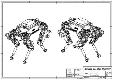
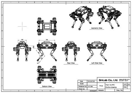
Click here to see all Orthographic Drawings.