Difference between revisions of "Joint Zeros and Directions Setup Guide"
Alexalspach (Talk | contribs) (→Encoder Directions) |
Alexalspach (Talk | contribs) (→Encoder Offsets) |
||
| Line 47: | Line 47: | ||
First, one should manually place all joints in their zero position. To do this, one must remove the hardware stop screw behind the thumb joint. The hand's zero position includes all fingers, including the thumb, outstretched so that the hand is flat. All finger links should be aligned and the finger yaw joints should align with the palm plane. Once the joints are in their zero position, we can read the encoder values to determine the offset values necessary to make this position zero. | First, one should manually place all joints in their zero position. To do this, one must remove the hardware stop screw behind the thumb joint. The hand's zero position includes all fingers, including the thumb, outstretched so that the hand is flat. All finger links should be aligned and the finger yaw joints should align with the palm plane. Once the joints are in their zero position, we can read the encoder values to determine the offset values necessary to make this position zero. | ||
| + | |||
| + | '''''Note:''' You may have to support the thumb which reading the values as gravity will make it sag from the set position.'' | ||
There are two buttons below the motion buttons entitled ''Test Encoders'' and ''Test Motors''. Press the button entitled ''Test Encoders'' and the current raw encoder values will print to the terminal window likely hidden behind the AAS main window. These values correspond to each joint in the order where ''enc_11 = 1'', end ''enc_23 = 7'', etc. The values printed are the exact values that must be input into each corresponding encoder device file's ''offset'' field. | There are two buttons below the motion buttons entitled ''Test Encoders'' and ''Test Motors''. Press the button entitled ''Test Encoders'' and the current raw encoder values will print to the terminal window likely hidden behind the AAS main window. These values correspond to each joint in the order where ''enc_11 = 1'', end ''enc_23 = 7'', etc. The values printed are the exact values that must be input into each corresponding encoder device file's ''offset'' field. | ||
| Line 52: | Line 54: | ||
[[Image:ZeroAndDir.jpg|400px]] | [[Image:ZeroAndDir.jpg|400px]] | ||
| − | |||
==Motor Directions== | ==Motor Directions== | ||
Revision as of 12:39, 22 October 2012
While your Allegro Application Studio installation was customized for your specific Allegro Hand hardware, there may arise a time when it is necessary to re-zero the joints or edit the encoder or motor directions.
This procedure may be necessary after replacing a servo or even just reassembling a joint after maintenance. With the tools provided, editing the joint zeros and directions is a simple process.
Encoder Directions
To test the encoder directions is simple. Just load Allegro Application Studio (AAS) with your hand plugged in and turned on. If you are unsure of how to use AAS with your Allegro Hand please refer to the Allegro Application Studio (User Manual).
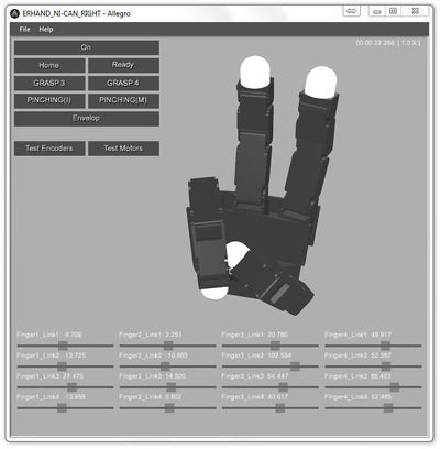
When Allegro Application Studio is loaded, press the On button to connect the virtual and actual hands. You can now see the finger joints on the virtual hand jump to possibly arbitrary positions. If the virtual joint positions to not match the actual joint positions, this indicates that the encoder offsets and/or directions are incorrect.
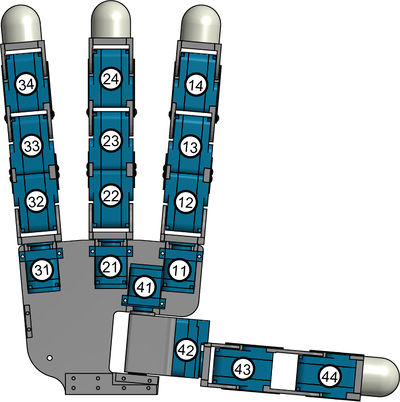
To test the encoder directions, simply rotate each of the sixteen (16) joints on the actual hand one at a time while watching the virtual hand in AAS. If any of the joints rotates the opposite direction, the encoder direction needs to be changed. On both the left and right hands, the joints are numbered as follows:
TABLE?
To edit the encoder direction for a specific joint, the joint specific encoder device file must be edited. These devices can be found in the devices folder:
[Allegro Application Studio Install Directory]\bin\models\Etc\ERHand\devices
For a right hand, the encoder files are specified as enc_RT_## and the left hand encoders are endL_RT_##. The first number in the name of the encoder file indicates the finger number and the second number indicates the joint number (as seen below). For both hands, finger one (1) is the index finger, finger two (2) the middle finger, finger three (3) the pinky and finger four (4) the thumb. The contents of the file can be edited in any text editor but an editor meant for programming, like Notepad++ is suggested.
It can be seen in the guts of the encoder device file that that there are fields for both the encoder direction and offset. For each virtual hand joint whose rotational direction did not match that of the actual hand joint, the property direction should be changed. If it is a positive(+), change it to a negative(-). If negative, switch it to a positive.
<!-- enc_RT_24.DML -->
<?xml version="1.0" encoding="UTF-8" standalone="no" ?>

...

  <specification byte="4" period="0" physics="..\..\..\devices\rDeviceERHandEncoder.rdd">
    <property name="channel" value="0"/>
    <property name="direction" value="+"/>   <!-- Encoder Direction -->
    <property name="offset" value="-1105"/>    <!-- Encoder Offset -->
    <property name="system device name" value="COMM"/>
  </specification>

</Device>
Once this has been done for all of the incorrect joints, it is wise to reload AAS and check once again the joint encoder directions. If any are incorrect, go back in and switch the sign of those affected. Once all joint encoder directions are correct, it is time to edit the offsets.
Encoder Offsets
Zeroing the joint encoders is an even simpler process than changing the signs. Once again, load Allegro Application Studio (AAS) and push the On button to connect to the Allegro Hand.
First, one should manually place all joints in their zero position. To do this, one must remove the hardware stop screw behind the thumb joint. The hand's zero position includes all fingers, including the thumb, outstretched so that the hand is flat. All finger links should be aligned and the finger yaw joints should align with the palm plane. Once the joints are in their zero position, we can read the encoder values to determine the offset values necessary to make this position zero.
Note: You may have to support the thumb which reading the values as gravity will make it sag from the set position.
There are two buttons below the motion buttons entitled Test Encoders and Test Motors. Press the button entitled Test Encoders and the current raw encoder values will print to the terminal window likely hidden behind the AAS main window. These values correspond to each joint in the order where enc_11 = 1, end enc_23 = 7, etc. The values printed are the exact values that must be input into each corresponding encoder device file's offset field.
Motor Directions
| Whos here now: Members 0 Guests 0 Bots & Crawlers 1 |

